
UI Port Configuration
Principle
The first step is to update the VEE Port project: this project holds the build descriptor file (build.gradle.kts in SDK 6, module.ivy in SDK 5).
This update is done in several steps, described in the sections below.
Some steps are optional, depending on the capabilities of the hardware.
Warning
This chapter assumes that a valid VEE Port has been created, as described in the chapter
Create a VEE Port in SDK 6
Create a VEE Port in SDK 5
UI Pack Selection
The UI Pack bundles several modules, including the Graphics Engine. The Graphics Engine is a library already compiled for an MCU and a C compiler. The MicroEJ Central Repository provides UI Packs for a set of MCU/Compiler pairs (like for MicroEJ Architectures).
Refer to the chapter Pack Import to add the required UI Pack. As an example, the module dependency to add for a Cortex-M4 and GCC toolchain would be:
dependencies {
   microejPack("com.microej.architecture.CM4.CM4hardfp_GCC48:flopi4G25-ui-pack:[UI Pack version]")
}
<dependencies>
   <!-- MicroEJ Architecture Specific Pack -->
   <dependency org="com.microej.architecture.CM4.CM4hardfp_GCC48" name="flopi4G25-ui-pack" rev="[UI Pack version]"/>
</dependencies>
Note
The latest version of the UI Pack is 14.5.2.
UI Pack Modules
The following sections describe each module that comes with the UI Pack (purpose and configuration).
The modules provided by the UI Pack are not installed by default. When a module is required, it has to be enabled and configured using the VEE Port Editor.
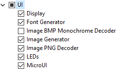
UI Pack Modules
Refer to the chapter Platform Module Configuration to add the UI Pack modules.
Module MicroUI
MicroUI is a Foundation Library that defines a Low Level UI framework (refer to the chapter MicroUI for more information). The mandatory module MicroUI (it must be checked in the VEE Port configuration file) provides the MicroUI implementation library. It requires a static initialization step to specify what MicroUI features are available for the application layer:
Create the file
[VEE Port project]/extensions/microui/microui.xmlin SDK 6[VEE Port Configuration project]/microui/microui.xmlin SDK 5
Edit the file as described here: Static Initialization.
<microui>

    <display name="DISPLAY"/>

    <eventgenerators>
        <command name="COMMANDS"/>
        <buttons name="BUTTONS" extended="3"/>
        <buttons name="JOYSTICK" extended="5"/>
        <touch name="TOUCH" display="DISPLAY"/>
    </eventgenerators>

    <fonts>
        <font file="resources\fonts\myfont.ejf"/>
    </fonts>

</microui>
Module LEDs
MicroUI provides some API to manipulate the LEDs. This module allows the UI Port to drive the LEDs. Refer to the chapter LED to have more information.
This module is optional: when not selected, a stub implementation is used, and the UI Port does not need to provide one.
Modules Image Decoders
Note
This chapter only applies when the device has a display.
This module adds an internal image decoder: it allows the application to embed an encoded image (e.g., PNG or BMP Monochrom) and let the Graphics Engine decode it at runtime. Both decoders (PNG and BMP Monochrom) are optional and can be selected (or not) independently. Refer to the chapter Encoded Image to have more information.
This module is optional: when no image decoder is embedded, the Graphics Engine relies on the UI Port (thanks to Abstraction Layer API) to decode the images.
Module Image Generator
Note
This chapter only applies when the device has a display.
This module allows decoding the application’s images at compile-time. The application’s images are decoded and stored in a binary format compatible with the Graphics Engine. The memory footprint of the application is higher, but the image loading time at runtime is very low. Refer to the chapter Image Generator to have more information.
This module is optional: when not selected, the application cannot embed generated images compatible with the Graphics Engine.
Module Font Generator
Note
This chapter only applies when the device has a display.
This module allows for embedding the MicroEJ bitmap fonts of the application. The application’s fonts are decoded and stored in a binary format compatible with the Graphics Engine. Refer to the chapter Font Generator to have more information.
This module is optional: when not selected, the application cannot embed fonts compatible with the Graphics Engine.
Module Display
Note
This chapter only applies when the device has a display.
This chapter takes the concepts described in chapter Display. The first step is determining the kind of display: size, pixel format, and constraints. This information will be used later by the UI Port configuration project, the Simulator extension project, and the BSP.
Size
The size is expressed in pixels, often 320x240 or 480x272.
This size defines the area the application can target; it can retrieve this size by calling Display.getWidth() and Display.getHeight().
It is always a rectangular area, even for the rounded displays (a square area frames a rounded display).
The display size is fixed for a display: retrieve this size in the board’s datasheet.
Pixel Format
The display pixel format (or pixel structure) gives two notions: the number of bits-per-pixel and the organization of color components in these bits.
The number of bits-per-pixel (bpp) is an integer value among this list: 1, 2, 4, 8, 16, 24, or 32.
The color components organization defines how the color components (Red, Green, and Blue) are distributed in the pixel.
The greater the display pixel format (in bits), the better is the definition.
This format also indicates the number of bits-per-pixel.
For instance, the format RGB565 is a 16-BPP format, indicating that the five MSB bits are for the Red color component, the six next bits are for the Green component, and the five LSB bits are for the Blue component.
This pixel format can be symbolized by RRRRRGGGGGGBBBBB or RRRR RGGG GGGB BBBB.
The display pixel format is often fixed by the display itself (its capabilities) and by the memory bus between the MCU and the LCD module.
However, the display pixel format is often configurable by the LCD controller.
Note that the number of bits-per-pixel and the display size fix the required memory to allocate: memory_size = width x height x bpp / 8.
Consequently, the pixel format may be less precise than the display capabilities depending on the memory available on the device.
For instance, the RGB565 format may be used whereas the display is a 24-bit display (RGB888).
Constraints
The hardware constraints (display, bus, memory, etc.) may drive the configuration:
The pixel format: Some hardware cannot use another pixel format other than the one of the display. This format may be standard or custom. See Pixel Structure.
The size of the buffers: The available memory may be limited. This limitation can drive the chosen pixel format.
Memory alignment: Some LCD controllers require a memory alignment on the display front buffer (alignment on 64 bits, for instance).
Buffer width alignment: Some LCD controllers also require an alignment for each line. The line size (in pixels) in memory may be larger than the display line size (width): this is the stride. The alignment constraint may be expressed in pixels or bytes. The required memory to allocate becomes:
memory_size = stride (in pixels) x height x bpp / 8.
Configuration
In the configuration.properties file of the VEE Port project,
fill the file as described here: Installation, according to the pixel format and the display constraints.
com.microej.pack.display.bpp=rgb565
com.microej.pack.display.imageBuffer.memoryAlignment=32
com.microej.pack.display.memoryLayout=line
com.microej.pack.display.byteLayout=line
In the VEE Port Configuration project:
Create the file
[VEE Port Configuration project]/display/display.propertiesFill the file as described here: Installation, according to the pixel format and the display constraints.
bpp=rgb565
imageBuffer.memoryAlignment=32
memoryLayout=line
byteLayout=line
VEE Port Build
Once modules are selected and configured, the VEE Port can be built again; see VEE Port Build.