
Display
Principle
The Display module contains the C part of the MicroUI implementation, which manages graphical displays. This module is composed of three elements:
the C part of MicroUI Display API (a built-in C archive) called Graphics Engine,
an implementation of Abstraction Layer APIs for the displays (LLUI_DISPLAY) that the BSP must provide (see LLUI_DISPLAY: Display),
an implementation of Abstraction Layer APIs for MicroUI drawings.
The Display module implements the MicroUI graphics framework.
This framework is constituted of several notions: the display characteristics (size, format, backlight, contrast, etc.), the drawing state machine (render, flush, wait flush completed), the image life cycle, and the fonts and drawings.
The main part of the Display module is provided by a built-in C archive called Graphics Engine.
This library manages the drawing state machine mechanism, the images, and the fonts.
The LLUI_DISPLAY implementation manages the display characteristics and the drawings.
The Graphics Engine is designed to let the BSP use an optional graphics processor unit (GPU) or an optional third-party drawing library. Each drawing can be implemented independently. If no extra framework is available, the Graphics Engine performs all drawings in software. In this case, the BSP has to perform a straightforward implementation (four functions) of the Graphics Engine Abstraction Layer.
MicroUI library also gives the possibility to perform some additional drawings that are not available as API in the MicroUI library. The Graphics Engine provides a set of functions to synchronize the drawings between them, to get the destination (and sometimes source) characteristics, to call internal software drawings, etc.
Front Panel (simulator Graphics Engine part) gives the same possibilities. The same constraints can be applied, the same drawings can be overridden or added, and the same software drawing rendering is performed (down to the pixel).
Chapters Organization
For more convenience, this chapter only describes how a display device works and how to connect it to the MicroUI Graphics Engine. Dedicated chapters deal with related concepts:
Buffer Refresh Strategy: how the front buffer is refreshed.
Drawings: how the drawings are performed, the use of a GPU, etc.
Images: how the images are generated and drawn.
Fonts: how the fonts are generated and drawn.
C Modules: how the BSP extends the Graphics Engine.
Simulation: how the Graphics Engine is simulated.
Display Configuration
The Graphics Engine provides a number of different configurations. The appropriate configuration should be selected depending on the capabilities of the screen and other related hardware, such as display controllers.
The policies can vary in four ways:
the display device connection to the Graphics Engine,
the number of buffers,
pixel format or depth,
the memory layout of the pixels.
Display Connection
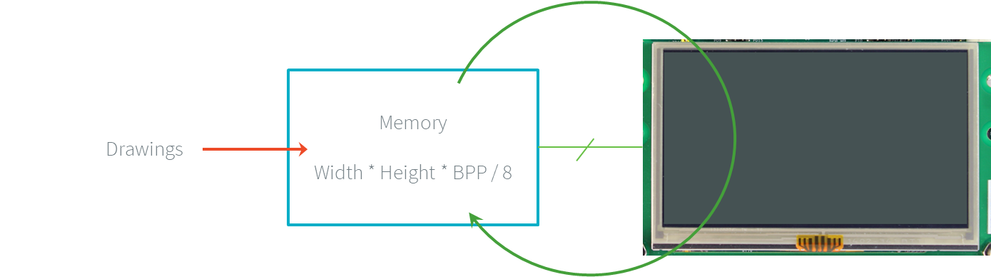
A display is always associated with a memory buffer whose size depends on the display panel size (width and height) and the number of bits per pixel. This memory buffer holds all the pixels the display panel has to show. The display panel continuously refreshes its content by reading the data from a memory buffer. This refreshing cannot be stopped; otherwise, the image fades away. Most of the time, a new frame often appears every 16.6ms (60Hz).
Display Continuous Refresh
There are two types of connection with the MCU: Serial and Parallel.
Serial
The MCU transmits the data to show (the pixels) to the display module through a serial bus (SPI, DSI). The display module holds its memory and fills it with the received data. It continuously refreshes its content by reading the data from this memory. This memory is usually not accessible to the MCU: the MCU can only write into it with the right macro (SPI or DSI). This is the notion of unmapped memory.
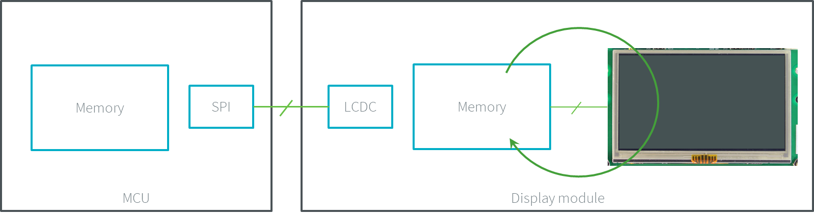
Display Serial Connection
Parallel
The MCU features an LCD controller that transmits the content of an MCU’s buffer to the display module. The display module doesn’t hold its memory. The LCD controller continuously updates the display panel’s content by reading the MCU memory data. By definition, this memory is addressed by the MCU: the MCU can write (and read) into it (the memory is in the MCU addresses range). This is the notion of mapped memory.
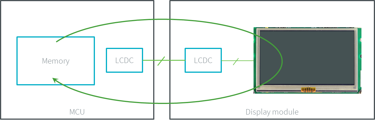
Display Parallel Connection
Buffer Policy
Overview
The notion of buffer policy depends on the available number of buffers allocated in the MCU memory and on the display connection. The Graphics Engine does not depend on the type of buffer policy, and it manipulates these buffers in two steps:
It renders the application drawings into an MCU buffer; this buffer is called back buffer.
It flushes the buffer’s content to the display panel; this buffer is called front buffer.
The implementation of Display.flush() calls the Abstraction Layer API LLUI_DISPLAY_IMPL_flush to let the BSP update the display data.
Decision Tree
The following flow charts provide handy guides to pick the buffer policy suited to the hardware configuration.
Serial Connection
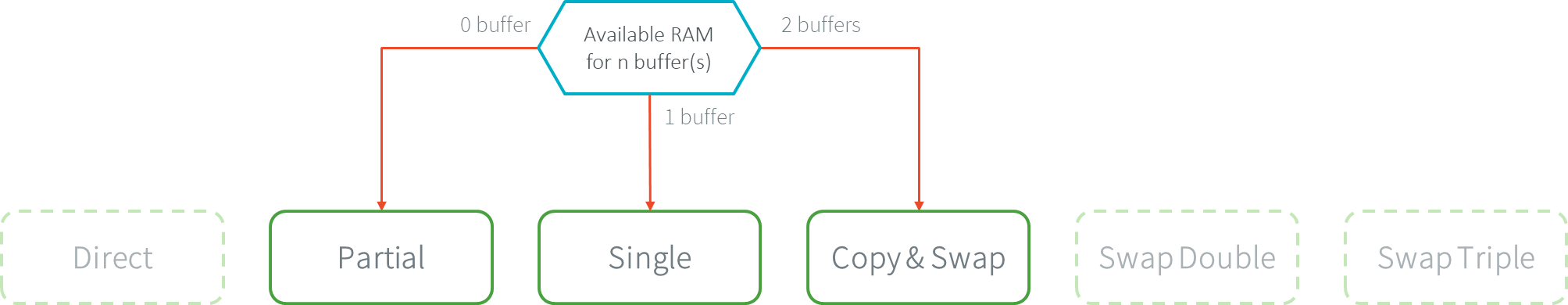
Buffer Policies for Serial Connection
Parallel Connection
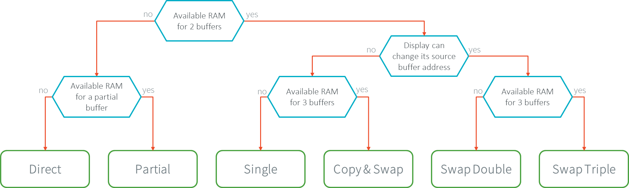
Buffer Policies for Parallel Connection
Chapter Sum-up
The following table redirects to the right chapter according to the display buffer policy:
Connection |
Nb MCU Buffers |
Chapters |
|---|---|---|
Serial |
partial |
|
Serial |
1 |
|
Serial |
2 |
|
Parallel |
1 |
|
Parallel |
1 + partial |
|
Parallel |
2 |
|
Parallel |
3 |
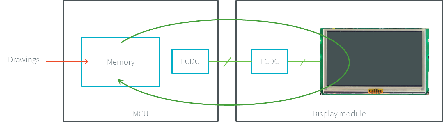
Direct Buffer (parallel)
There is only one buffer, and the display panel continuously refreshes its content on this MCU buffer. This MCU buffer is, at the same time, the back and front buffer. Consequently, the display panel can show incomplete frames and partial drawings since the drawings can be done during the refresh cycle of the display panel. This is the notion of direct buffer. This buffer policy is recommended for static display-based applications and/or to save memory.
In this policy, the flush step has no meaning (there is only one buffer).
Direct Buffer
Swap Double Buffer (parallel)
To prevent flickering in the display panel, the BSP should provide another MCU buffer (the same size as the first buffer) where the drawings are performed. The first buffer, for its part, is dedicated to the refreshing of the display panel. Double buffering avoids flickering and inconsistent rendering: it is well suited to high-quality animations. This is the notion of double buffer. This new buffer is usually called back buffer, and the first buffer is usually called front buffer. The two buffers in MCU memory alternately play the role of the back buffer and the front buffer. The front buffer address is alternatively changed from one buffer to the other.
The flush step consists in switching (or swapping) the two buffers: the front buffer becomes the back buffer, and the back buffer becomes the front buffer.
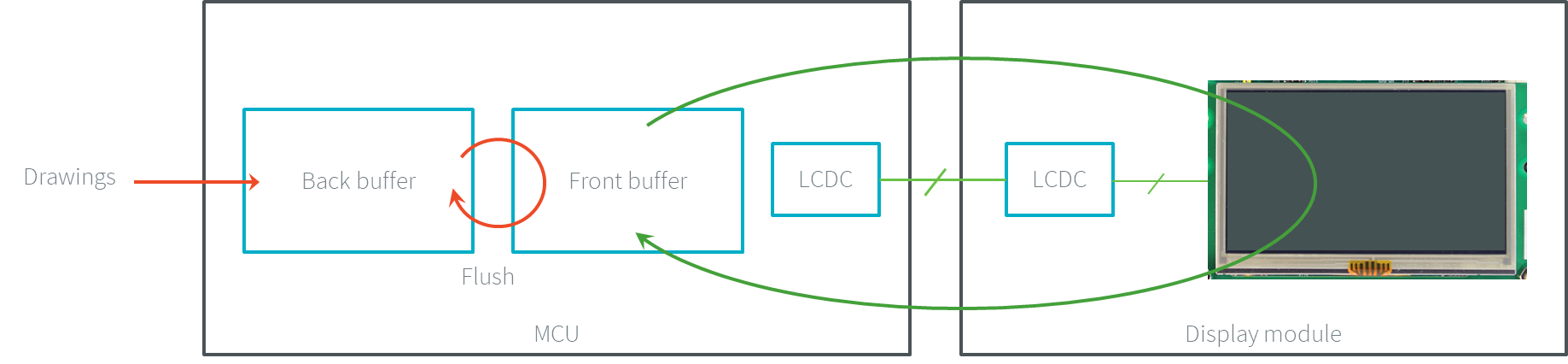
Swap Double Buffer
This swap may not be atomic and may be done asynchronously: the display panel often fully refreshes an entire frame before changing its buffer address. During this time, the front buffer is used (the display panel refreshes itself on it), and the back buffer is locked (reserved for the next frame to show). Consequently, the application cannot draw again: the swapping must be performed before. As soon as the swap is done, both buffers are switched. Now, the application can draw in the new back buffer (previously the front buffer).
Swap Triple Buffer (parallel)
When the display is large, it is possible to introduce a third mapped buffer. This third buffer saves from waiting the end of the swapping before starting a new drawing. The buffers are usually called back buffer 1, back buffer 2, and back buffer 3.
The flush step consists in swapping two buffers and letting the application draw in the third buffer:
The back buffer 1 is the front buffer: it is currently used by the LCD controller to refresh the display panel.
The back buffer 2 is the next front buffer: the drawings have been done, and a flush is requested.
The back buffer 3 is not used: the application can immediately draw into it without waiting for the swapping between the back buffers 1 & 2.
When the drawings are done in the back buffer 3, this buffer becomes the next front buffer, the back buffer 2 is the front buffer, and the back buffer 1 is free.
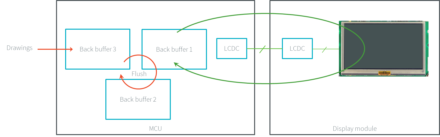
Swap Triple Buffer
Single Buffer
Serial Connection
For the display connection serial, there are two distinct buffers: the buffer where the drawings are rendered is usually called back buffer, and the display module buffer front buffer. As long as only the back buffer is stored in the MCU-mapped memory (the front buffer is stored in the display module unmapped memory), there is only one buffer to allocate. This is the notion of single buffer.
The flush step consists in transmitting the data through the right bus (SPI, DSI).
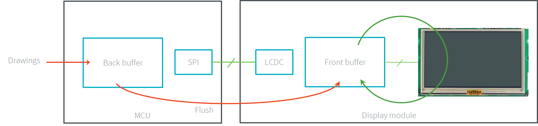
Single Buffer (serial)
The display panel only shows complete frames; it cannot show partial drawings because the flush step is performed after all the drawings. The application cannot draw in the back buffer while the data is transmitted to the front buffer. As soon as the data is fully transmitted, the application can draw again in the back buffer.
The time to transmit the data from the back buffer to the front buffer may be long. During this time, no drawing can be anticipated, and the global framerate is reduced.
Parallel Connection
When the swap policy is not possible (the front buffer is mapped on a fixed MCU memory address), the policy single buffer can be used. Like the swap policy, this double buffering avoids flickering and inconsistent rendering: it is well suited to high-quality animations.
The flush step consists in copying the back buffer content to the front buffer (often by using a DMA).
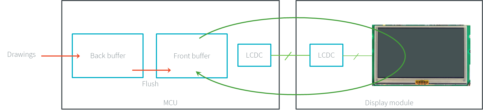
Single Buffer (parallel)
When the swap policy can be used, the single buffer policy can also be used. However, there are some differences:
In the Swap Double policy, the new front buffer data is available instantly. As soon as the LCD controller has updated its front buffer address, the data is ready to be read by the LCD controller. In the Single policy, the process of copying the data to the front buffer occurs while the LCD controller is reading it. Therefore, the buffer copy has to be faster than the LCD controller reading. If this requirement is not met, the LCD controller will read a mix of new and old data (because the buffer copy is not entirely finished).
In the Swap Double policy, the synchronization with the LCD controller is more effortless. An interrupt is thrown as soon as the LCD controller has updated its front buffer address. In the Single policy, the copy buffer process should be synchronized with the LCD tearing signal.
In the Single policy, during the copy, the destination buffer (the front buffer) is used by the copy buffer process (DMA, memcopy, etc.) and by the LCD controller. Both masters are using the same RAM section. This same RAM section switches in Write mode (copy buffer process) and Read mode (LCD controller).
Transmit and Swap Buffer
Serial Connection
When the time to transmit the data from the back buffer to the front buffer is too long, a second buffer can be allocated in the MCU memory. The application can use this buffer while the first buffer is transmitted. This allows to anticipate the drawings even if the first drawings are not fully transmitted. This is the notion of transmit and swap buffer. The buffers are usually called back buffer 1 and back buffer 2 (the display module’s buffer is the front buffer).
The flush step consists in transmitting the back buffer data to the display module memory and swapping both back buffers:
The back buffer 1 is used as transmission buffer.
The back buffer 2 is not used: the application can immediately draw into it without waiting for the back buffer 1 to be transmitted.
At the end of the drawings in the back buffer 2, the back buffer 2 takes the role of the transmission buffer, and the back buffer 1 is free.
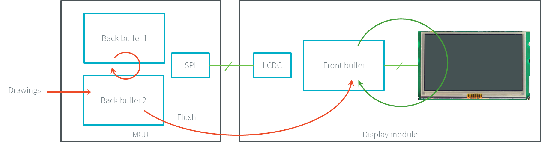
Transmit and Swap (serial)
Parallel Connection
When the time to copy the data from the back buffer to the front buffer is too long, a third buffer can be allocated in the MCU memory. This buffer can be used by the application during the copy of the first buffer. This allows to anticipate the drawings even if the first drawings still need to be entirely copied. This is the notion of transmit and swap buffer. The buffers are usually called back buffer 1 and back buffer 2 (the third buffer is the front buffer). The flush step consists in copying the back buffer data to the front buffer and swapping both back buffers.
The back buffer 1 is used as copying buffer.
The back buffer 2 is not used: the application can immediately draw into it without waiting for the back buffer 1 to be copied.
At the end of the drawings in the back buffer 2, the back buffer 2 takes the role of the copying buffer, and the back buffer 1 is free.
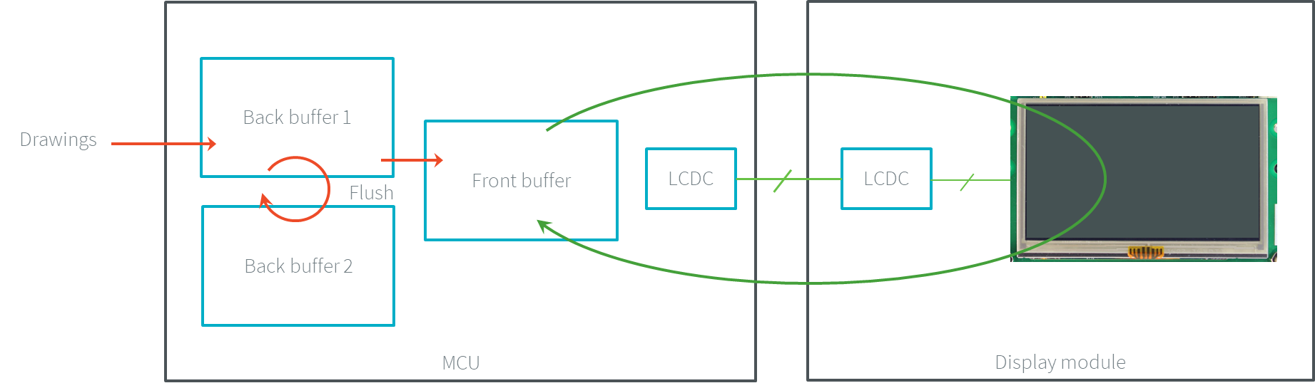
Transmit and Swap (parallel)
Partial Buffer
When RAM usage is not a constraint, the back buffer is sized to store all the pixel data of the screen. But when the RAM available on the device is very limited, a partial buffer can be used instead. In that case, the buffer is smaller and can only store a part of the screen (one-third, for example).
When this technique is used, the application draws in the partial buffer. To flush the drawings, the content of the partial buffer is copied to the display (to its internal memory or to a complete buffer from which the display reads).
If the display does not have its own internal memory and if the device does not have enough RAM to allocate a complete buffer, then it is not possible to use a partial buffer. In that case, only the direct buffer policy can be used.
Workflow
A partial buffer of the desired size has to be allocated in RAM. If the display does not have its own internal memory, a complete buffer also has to be allocated in RAM, and the display has to be configured to read from the whole buffer.
The implementation should follow these steps:
First, the application draws in the partial buffer.
Then, to flush the drawings on the screen, the data of the partial buffer is flushed to the display (either copied to its internal memory or the complete buffer in RAM).
Finally, synchronization is required before starting the next drawing operation.
Dual Partial Buffer
A second partial buffer can be used to avoid the synchronization delay between two drawing cycles. While one of the two partial buffers is being copied to the display, the application can start drawing in the second partial buffer.
This technique is interesting when the copy time is long. The downside is that it either requires more RAM or requires reducing the size of the partial buffers.
Using a dual partial buffer has no impact on the application code.
Application Limitations
Using a partial buffer rather than a complete buffer may require adapting the code of the application since rendering a graphical element may require multiple passes. If the application uses MWT, a custom render policy has to be used.
Besides, the GraphicsContext.readPixel() and the GraphicsContext.readPixels() APIs can not be used on the graphics context of the display in partial buffer policy. Indeed, we cannot rely on the current content of the back buffer as it doesn’t contain what is seen on the screen.
Likewise, the Painter.drawDisplayRegion() API can not be used in partial buffer policy. Indeed, this API reads the content of the back buffer in order to draw a region of the display. Instead of relying on the drawings that were performed previously, this API should be avoided, and the drawings should be performed again.
Using a partial buffer can have a significant impact on animation performance. Refer to Animations for more information on the development of animations in an application.
Implementation Example
The partial buffer demo provides an example of partial buffer implementation. This example explains how to implement partial buffer support in the BSP and how to use it in an application.
Pixel Structure
Principle
The Display module provides pre-built display configurations with a standard pixel memory layout.
The layout of the bits within the pixel may be standard or driver-specific.
When installing the Display module, a property bpp is required to specify the kind of pixel representation (see Installation).
Standard
When the value is one among this list: ARGB8888 | RGB888 | RGB565 | ARGB1555 | ARGB4444 | C4 | C2 | C1, the Display module considers the pixels representation as standard.
All standard representations are internally managed by the Display module, by the Front Panel and by the Image Generator.
No specific support is required as long as a VEE Port is using a standard representation.
It can:
generate at compile-time RAW images in the same format as display pixel format,
convert at runtime MicroUI 32-bit colors in display pixel format,
simulate the display pixel format at runtime.
Note
The custom implementations of the image generator, some Abstraction Layer APIs, and Front Panel APIs are ignored by the Display module when a standard pixel representation is selected.
According to the chosen format, some color data can be lost or cropped.
ARGB8888: the pixel uses 32 bits-per-pixel (alpha[8], red[8], green[8] and blue[8]).
u32 convertARGB8888toLCDPixel(u32 c) {
    return c;
}

u32 convertLCDPixeltoARGB8888(u32 c) {
    return c;
}
RGB888: the pixel uses 24 bits-per-pixel (alpha[0], red[8], green[8] and blue[8]).
u32 convertARGB8888toLCDPixel(u32 c) {
    return c & 0xffffff;
}

u32 convertLCDPixeltoARGB8888(u32 c) {
    return 0
            | 0xff000000
            | c
            ;
}
RGB565: the pixel uses 16 bits-per-pixel (alpha[0], red[5], green[6] and blue[5]).
u32 convertARGB8888toLCDPixel(u32 c) {
    return 0
            | ((c & 0xf80000) >> 8)
            | ((c & 0x00fc00) >> 5)
            | ((c & 0x0000f8) >> 3)
            ;
}

u32 convertLCDPixeltoARGB8888(u32 c) {
    return 0
            | 0xff000000
            | ((c & 0xf800) << 8)
            | ((c & 0x07e0) << 5)
            | ((c & 0x001f) << 3)
            ;
}
ARGB1555: the pixel uses 16 bits-per-pixel (alpha[1], red[5], green[5] and blue[5]).
u32 convertARGB8888toLCDPixel(u32 c) {
    return 0
            | (((c & 0xff000000) == 0xff000000) ? 0x8000 : 0)
            | ((c & 0xf80000) >> 9)
            | ((c & 0x00f800) >> 6)
            | ((c & 0x0000f8) >> 3)
            ;
}

u32 convertLCDPixeltoARGB8888(u32 c) {
    return 0
            | ((c & 0x8000) == 0x8000 ? 0xff000000 : 0x00000000)
            | ((c & 0x7c00) << 9)
            | ((c & 0x03e0) << 6)
            | ((c & 0x001f) << 3)
            ;
}
ARGB4444: the pixel uses 16 bits-per-pixel (alpha[4], red[4], green[4] and blue[4]).
u32 convertARGB8888toLCDPixel(u32 c) {
    return 0
            | ((c & 0xf0000000) >> 16)
            | ((c & 0x00f00000) >> 12)
            | ((c & 0x0000f000) >> 8)
            | ((c & 0x000000f0) >> 4)
            ;
}

u32 convertLCDPixeltoARGB8888(u32 c) {
    return 0
            | ((c & 0xf000) << 16)
            | ((c & 0xf000) << 12)
            | ((c & 0x0f00) << 12)
            | ((c & 0x0f00) << 8)
            | ((c & 0x00f0) << 8)
            | ((c & 0x00f0) << 4)
            | ((c & 0x000f) << 4)
            | ((c & 0x000f) << 0)
            ;
}
C4: the pixel uses 4 bits-per-pixel (grayscale[4]).
u32 convertARGB8888toLCDPixel(u32 c) {
    return (toGrayscale(c) & 0xff) / 0x11;
}

u32 convertLCDPixeltoARGB8888(u32 c) {
    return 0xff000000 | (c * 0x111111);
}
C2: the pixel uses 2 bits-per-pixel (grayscale[2]).
u32 convertARGB8888toLCDPixel(u32 c) {
    return (toGrayscale(c) & 0xff) / 0x55;
}

u32 convertLCDPixeltoARGB8888(u32 c) {
    return 0xff000000 | (c * 0x555555);
}
C1: the pixel uses 1 bit-per-pixel (grayscale[1]).
u32 convertARGB8888toLCDPixel(u32 c) {
    return (toGrayscale(c) & 0xff) / 0xff;
}

u32 convertLCDPixeltoARGB8888(u32 c) {
    return 0xff000000 | (c * 0xffffff);
}
Driver-Specific
The Display module considers the pixel representation as driver-specific when the value is one among this list: 1 | 2 | 4 | 8 | 16 | 24 | 32.
This mode is often used when the pixel representation is not ARGB or RGB but BGRA or BGR instead.
This mode can also be used when the number of bits for a color component (alpha, red, green, or blue) is not standard or when the value does not represent a color but an index in a CLUT.
This mode requires some specific support in the VEE Port:
An extension of the image generator is mandatory: see Extended Mode to convert MicroUI’s standard 32-bit ARGB colors to display pixel format.
The Front Panel widget
Displayrequires an extension to convert the MicroUI 32-bit colors in display pixel format and vice-versa, see Display Widget.The driver must implement functions that convert MicroUI’s standard 32-bit ARGB colors to display pixel format and vice-versa: see Color Conversions.
The following example illustrates the use of specific format BGR565 (the pixel uses 16 bits-per-pixel (alpha[0], red[5], green[6] and blue[5]):
Configure the VEE Port:
In SDK 6, the configuration is done in the properties file
configuration.propertiesof the VEE Port project:com.microej.pack.display.bpp=16
In SDK 5, the configuration is done in the properties file
display/display.properties:bpp=16
Image Generator:
Create a project as described here.
Create the class
com.microej.graphicalengine.generator.MicroUIGeneratorExtensionthat extends the classcom.microej.tool.ui.generator.BufferedImageLoader.Fill the method
convertARGBColorToDisplayColor():public class MicroUIGeneratorExtension extends BufferedImageLoader { @Override public int convertARGBColorToDisplayColor(int color) { return ((color & 0xf80000) >> 19) | ((color & 0x00fc00) >> 5) | ((color & 0x0000f8) << 8); } }
Configure the Image Generator’ service loader: add the file
/META-INF/services/com.microej.tool.ui.generator.MicroUIRawImageGeneratorExtension:com.microej.graphicalengine.generator.MicroUIGeneratorExtension
Build the module (click on the blue button).
Copy the generated jar file (
imageGeneratorMyPlatform.jar) in the VEE Port configuration project:/dropins/tools/.
Simulator (Front Panel):
Create the class
com.microej.fp.MyDisplayExtensionthat implements the interfaceej.fp.widget.Display.DisplayExtension:
public class MyDisplayExtension implements DisplayExtension {

   @Override
   public int convertARGBColorToDisplayColor(Display display, int color) {
      return ((color & 0xf80000) >> 19) | ((color & 0x00fc00) >> 5) | ((color & 0x0000f8) << 8);
   }

   @Override
   public int convertDisplayColorToARGBColor(Display display, int color) {
      return ((color & 0x001f) << 19) | ((color & 0x7e00) << 5) | ((color & 0xf800) >> 8) | 0xff000000;
   }

   @Override
   public boolean isColor(Display display) {
      return true;
   }

   @Override
   public int getNumberOfColors(Display display) {
      return 1 << 16;
   }
}
Configure the widget
Displayin the.fpfile by referencing the display extension:
<ej.fp.widget.Display x="41" y="33" width="320" height="240" extensionClass="com.microej.fp.MyDisplayExtension"/>
Build the VEE Port as usual
Update the
LLUI_DISPLAYimplementation by adding the following functions:uint32_t LLUI_DISPLAY_IMPL_convertARGBColorToDisplayColor(uint32_t color) { return ((color & 0xf80000) >> 19) | ((color & 0x00fc00) >> 5) | ((color & 0x0000f8) << 8); } uint32_t LLUI_DISPLAY_IMPL_convertDisplayColorToARGBColor(uint32_t color) { return ((color & 0x001f) << 19) | ((color & 0x7e00) << 5) | ((color & 0xf800) >> 8) | 0xff000000; }
CLUT
The Display module allows the targeting of a display that uses a pixel indirection table (CLUT). This kind of display is considered as generic but not standard (see Pixel Structure). It consists in storing color indexes in the image memory buffer instead of colors themselves.
Color Conversion
The driver must implement functions that convert MicroUI’s standard 32-bit ARGB colors (see LLUI_DISPLAY: Display) to display color representation. For each application ARGB8888 color, the display driver has to find the corresponding color in the table. The Graphics Engine will store the index of the color in the table instead of using the color itself.
When an application color is not available in the display driver table (CLUT), the display driver can try to find the closest color or return a default color. The first solution is often quite tricky to write and can cost a lot of time at runtime. That’s why the second solution is preferred. However, a consequence is that the application only uses a range of colors provided by the display driver.
Alpha Blending
MicroUI and the Graphics Engine use blending when drawing some texts or anti-aliased shapes. For each pixel to draw, the display stack blends the current application foreground color with the targeted pixel’s current color or with the current application background color (when enabled). This blending creates some intermediate colors which the display driver manages.
Most of the time, the intermediate colors do not match with the palette.
The default color is so returned, and the rendering becomes wrong.
To prevent this use case, the Graphics Engine offers a specific Abstraction Layer API LLUI_DISPLAY_IMPL_prepareBlendingOfIndexedColors(void *foreground, void *background).
This API is only used when a blending is required and when the background color is enabled. The Graphics Engine calls the API just before the blending and gives as a parameter the pointers on both ARGB colors.The display driver should replace the ARGB colors with the CLUT indexes. Then, the Graphics Engine will only use between both indexes.
For instance, when the returned indexes are 20 and 27, the display stack will use the indexes 20 to 27, where all indexes between 20 and 27 target some intermediate colors between both the original ARGB colors.
This solution requires several conditions:
Background color is enabled, and it is an available color in the CLUT.
The application can only use foreground colors provided by the CLUT. The VEE Port designer should give to the application developer the available list of colors the CLUT manages.
The CLUT must provide a set of blending ranges the application can use. Each range can have its own size (different number of colors between two colors). Each range is independent. For instance, if the foreground color
RED(0xFFFF0000) can be blended with two background colorsWHITE(0xFFFFFFFF) andBLACK(0xFF000000), two ranges must be provided. Both the ranges have to contain the same index for the colorRED.Application can only use blending ranges provided by the CLUT. Otherwise, the display driver is not able to find the range, and the default color will be used to perform the blending.
Rendering of dynamic images (images decoded at runtime) may be wrong because the ARGB colors may be out of the CLUT range.
Memory Layout
For the display with a number of bits-per-pixel (BPP) higher or equal to 8, the Graphics Engine supports the line-by-line memory organization: pixels are laid out from left to right within a line, starting with the top line. For a display with 16 bits-per-pixel, the pixel at (0,0) is stored at memory address 0, the pixel at (1,0) is stored at address 2, the pixel at (2,0) is stored at address 4, and so on.
BPP |
@ + 0 |
@ + 1 |
@ + 2 |
@ + 3 |
@ + 4 |
|---|---|---|---|---|---|
32 |
pixel 0 [7:0] |
pixel 0 [15:8] |
pixel 0 [23:16] |
pixel 0 [31:24] |
pixel 1 [7:0] |
24 |
pixel 0 [7:0] |
pixel 0 [15:8] |
pixel 0 [23:16] |
pixel 1 [7:0] |
pixel 1 [15:8] |
16 |
pixel 0 [7:0] |
pixel 0 [15:8] |
pixel 1 [7:0] |
pixel 1 [15:8] |
pixel 2 [7:0] |
8 |
pixel 0 [7:0] |
pixel 1 [7:0] |
pixel 2 [7:0] |
pixel 3 [7:0] |
pixel 4 [7:0] |
For the display with a number of bits-per-pixel (BPP) lower than 8, the Graphics Engine supports both memory organizations: line by line (pixels are laid out from left to right within a line, starting with the top line) and column by column (pixels are laid out from top to bottom within a line, starting with the left line).
These byte organizations concern until 8 consecutive pixels (see Byte Layout).
When installing the Display module, a property memoryLayout is required to specify the kind of pixel representation (see Installation).
BPP |
@ + 0 |
@ + 1 |
@ + 2 |
@ + 3 |
@ + 4 |
|---|---|---|---|---|---|
4 |
(0,0) to (1,0) |
(2,0) to (3,0) |
(4,0) to (5,0) |
(6,0) to (7,0) |
(8,0) to (9,0) |
2 |
(0,0) to (3,0) |
(4,0) to (7,0) |
(8,0) to (11,0) |
(12,0) to (15,0) |
(16,0) to (19,0) |
1 |
(0,0) to (7,0) |
(8,0) to (15,0) |
(16,0) to (23,0) |
(24,0) to (31,0) |
(32,0) to (39,0) |
BPP |
@ + 0 |
@ + 1 |
@ + 2 |
@ + 3 |
@ + 4 |
|---|---|---|---|---|---|
4 |
(0,0) to (0,1) |
(1,0) to (1,1) |
(2,0) to (2,1) |
(3,0) to (3,1) |
(4,0) to (4,1) |
2 |
(0,0) to (0,3) |
(1,0) to (1,3) |
(2,0) to (2,3) |
(3,0) to (3,3) |
(4,0) to (4,3) |
1 |
(0,0) to (0,7) |
(1,0) to (1,7) |
(2,0) to (2,7) |
(3,0) to (3,7) |
(4,0) to (4,7) |
BPP |
@ + 0 |
@ + 1 |
@ + 2 |
@ + 3 |
@ + 4 |
|---|---|---|---|---|---|
4 |
(0,0) to (1,0) |
(0,1) to (1,1) |
(0,2) to (1,2) |
(0,3) to (1,3) |
(0,4) to (1,4) |
2 |
(0,0) to (3,0) |
(0,1) to (3,1) |
(0,2) to (3,2) |
(0,3) to (3,3) |
(0,4) to (3,4) |
1 |
(0,0) to (7,0) |
(0,1) to (7,1) |
(0,2) to (7,2) |
(0,3) to (7,3) |
(0,4) to (7,4) |
BPP |
@ + 0 |
@ + 1 |
@ + 2 |
@ + 3 |
@ + 4 |
|---|---|---|---|---|---|
4 |
(0,0) to (0,1) |
(0,2) to (0,3) |
(0,4) to (0,5) |
(0,6) to (0,7) |
(0,8) to (0,9) |
2 |
(0,0) to (0,3) |
(0,4) to (0,7) |
(0,8) to (0,11) |
(0,12) to (0,15) |
(0,16) to (0,19) |
1 |
(0,0) to (0,7) |
(0,8) to (0,15) |
(0,16) to (0,23) |
(0,24) to (0,31) |
(0,32) to (0,39) |
Byte Layout
This chapter concerns only displays with a number of bits-per-pixel (BPP) smaller than 8. For this kind of display, a byte contains several pixels, and the Graphics Engine allows to customize how to organize the pixels in a byte.
Two layouts are available:
line: The byte contains several consecutive pixels on the same line. When the end of the line is reached, padding is added in order to start a new line with a new byte.
column: The byte contains several consecutive pixels on the same column. When the end of the column is reached, padding is added in order to start a new column with a new byte.
When installing the Display module, a property byteLayout is required to specify the kind of pixel representation (see Installation).
BPP |
MSB |
LSB |
||||||
|---|---|---|---|---|---|---|---|---|
4 |
pixel 1 |
pixel 0 |
||||||
2 |
pixel 3 |
pixel 2 |
pixel 1 |
pixel 0 |
||||
1 |
pixel 7 |
pixel 6 |
pixel 5 |
pixel 4 |
pixel 3 |
pixel 2 |
pixel 1 |
pixel 0 |
BPP |
4 |
2 |
1 |
|---|---|---|---|
MSB |
pixel 1 |
pixel 3 |
pixel 7 |
pixel 6 |
|||
pixel 2 |
pixel 5 |
||
pixel 4 |
|||
pixel 0 |
pixel 1 |
pixel 3 |
|
pixel 2 |
|||
pixel 0 |
pixel 1 |
||
LSB |
pixel 0 |
Display Synchronization
Overview
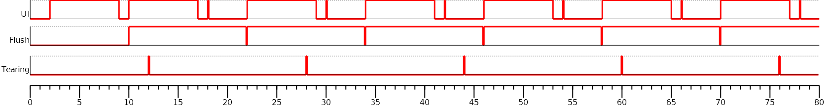
The Graphics Engine is designed to be synchronized with the display refresh rate by defining some points in the rendering timeline. It is optional; however, it is mainly recommended. This chapter explains why to use display tearing signal and its consequences. Some chronograms describe several use cases: with and without display tearing signal, long drawings, long flush time, etc. Times are in milliseconds. To simplify chronograms views, the display refresh rate is every 16ms (62.5Hz).
Captions definition:
UI: It is the UI task that performs the drawings in the back buffer. At the end of the drawings, the examples consider that the UI thread calls Display.flush() 1 millisecond after the end of the drawings. At this moment, a flush can start (the call to Display.flush() is symbolized by a simple peak in chronograms).
Flush: In single buffer policy, it is the time to flush the content of the back buffer to the front buffer. In double or triple policy, it is the time to swap back and front buffers (the instruction is often instantaneous but the action is usually performed at the beginning of the next display refresh rate). During this time, the back buffer is in use, and the UI task has to wait until the end of the swap before starting a new drawing.
Tearing: The peaks show the tearing signals.
Rendering frequency: the frequency between the start of a drawing and the end of the flush.
Tearing Signal
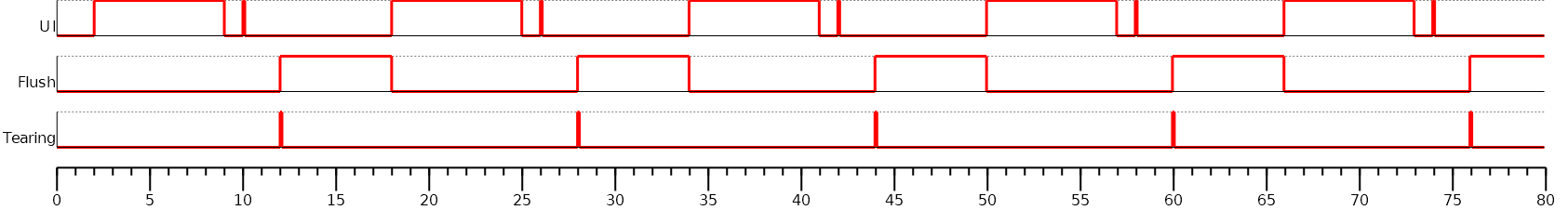
In this example, the drawing time is 7ms, the time between the end of the drawing and the call to Display.flush() is 1ms, and the flush time is 6ms. So the expected rendering frequency is 7 + 1 + 6 = 14ms (71.4Hz). Flush starts just after the call to Display.flush(), and the next drawing starts just after the end of flush. Tearing signal is not taken into consideration. As a consequence, the display content is refreshed during the display refresh time. The content can be corrupted: flickering, glitches, etc. The rendering frequency is faster than the display refresh rate.

In this example, the times are identical to the previous example. The tearing signal is used to start the flush to respect the display refreshing time. The rendering frequency becomes smaller: it is cadenced on the tearing signal every 16ms (62.5Hz). During 2ms, the CPU can schedule other tasks or go into idle mode. The rendering frequency is equal to the display refresh rate.
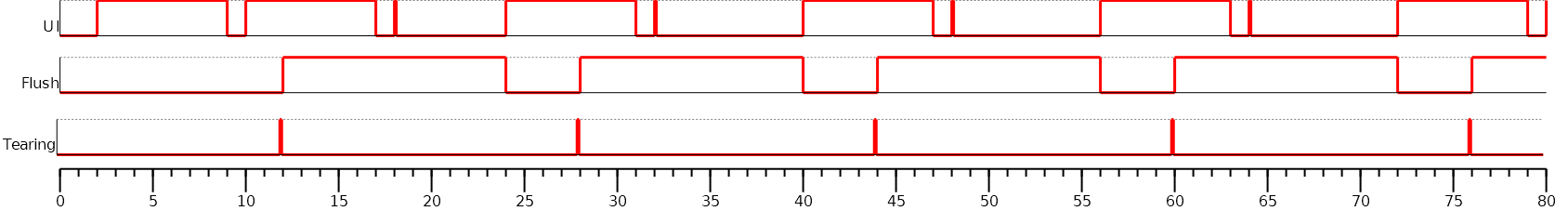
In this example, the drawing time is 14ms, the time between the end of the drawing and the call to Display.flush() is 1ms, and the flush time is 6ms. So the expected rendering frequency is 14 + 1 + 6 = 21ms (47.6Hz). Flush starts just after the call to Display.flush(), and the next drawing starts just after the end of flush. Tearing signal is not taken into consideration.
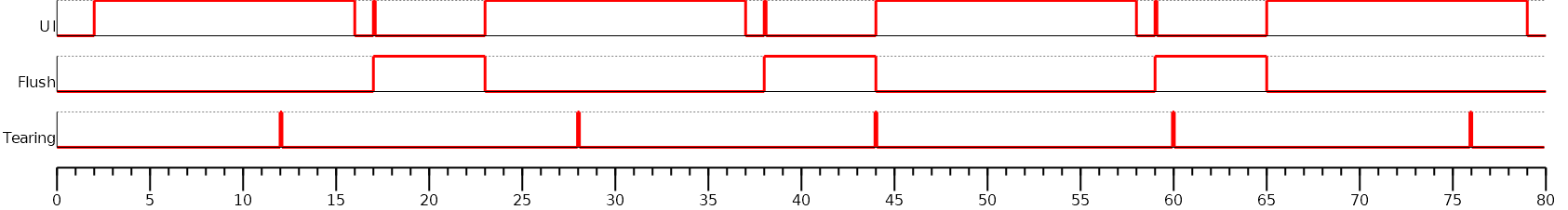
In this example, the times are identical to the previous example. The tearing signal is used to start the flush to respect the display refreshing time. The drawing time + flush time is higher than the display tearing signal period. So, the flush cannot start at every tearing peak: it is cadenced on two tearing signals every 32ms (31.2Hz). During 11ms, the CPU can schedule other tasks or go into idle mode. The rendering frequency is equal to the display refresh rate divided by two.
Additional Buffer
Some devices take a lot of time to flush the back buffer content to the front buffer. The following examples demonstrate the consequence of rendering frequency. The use of an additional buffer optimizes this frequency; however, it uses a lot of RAM.
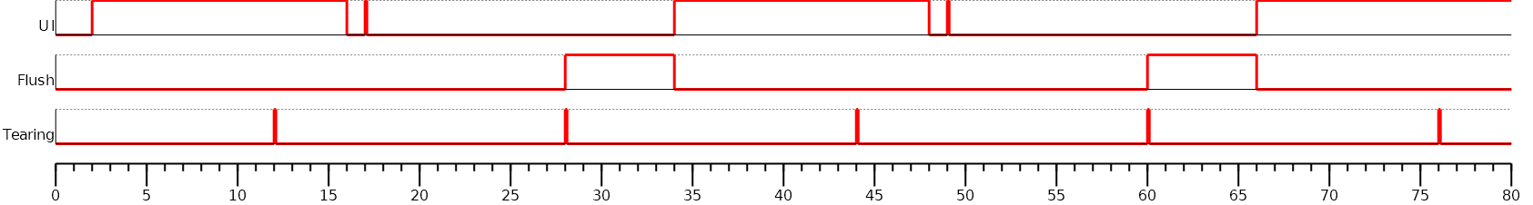
In this example, the drawing time is 7ms, the time between the end of the drawing and the call to Display.flush() is 1ms, and the flush time is 12ms. So the expected rendering frequency is 7 + 1 + 12 = 20ms (50Hz). Flush starts just after the call to Display.flush(), and the next drawing starts just after the end of flush. Tearing signal is not taken into consideration. The rendering frequency is cadenced on drawing time + flush time.
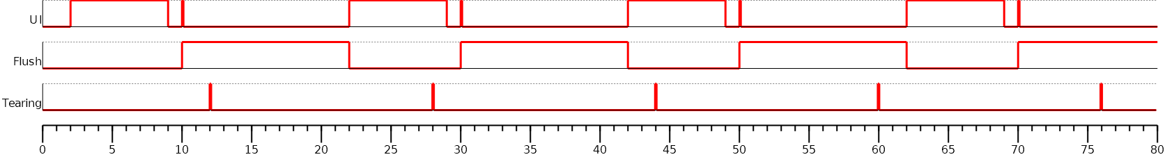
As mentioned above, the idea is to use two back buffers.
First, the UI task is drawing in the back buffer A.
Just after the call to Display.flush(), the flush can start.
During the flush time (copy of the back buffer A to the front buffer), the back buffer B can be used by the UI task to continue the drawings.
When the drawings in the back buffer B are done (and after the call to Display.flush()), the application cannot start a third frame by drawing into the back buffer A because the flush is using it.
As soon as the flush is done, a new flush (of the back buffer B) can start.
The rendering frequency is cadenced on flush time, i.e., 12ms (83.3Hz).
The previous example doesn’t take into consideration the display tearing signal. With a tearing signal and only one back buffer, the frequency is cadenced on two tearing signals (see above). With two back buffers, the frequency is now cadenced on only one tearing signal despite the long flush time.
Time Sum-up
The following table resumes the previous examples times:
It considers the display frequency is 62.5Hz (16ms).
Drawing time is the time left for the application to perform its drawings and call Display.flush(). In our examples, the time between the last drawing and the call to Display.flush() is 1 ms.
FPS and CPU load are calculated from examples times.
Max drawing time is the maximum time left for the application to perform its drawings without overlapping the next display tearing signal (when tearing is enabled).
Tearing |
Nb buffers |
Drawing time (ms) |
Flush time (ms) |
FPS (Hz) |
CPU load (%) |
Max drawing time (ms) |
no |
1 |
7+1 |
6 |
71.4 |
57.1 |
|
yes |
1 |
7+1 |
6 |
62.5 |
50 |
10 |
no |
1 |
14+1 |
6 |
47.6 |
71.4 |
|
yes |
1 |
14+1 |
6 |
31.2 |
46.9 |
20 |
no |
1 |
7+1 |
12 |
50 |
40 |
|
yes |
1 |
7+1 |
12 |
31.2 |
25 |
8 |
no |
2 |
7+1 |
12 |
83.3 |
66.7 |
|
yes |
2 |
7+1 |
12 |
62.5 |
50 |
16 |
Abstraction Layer API
Overview
Display Abstraction Layer API
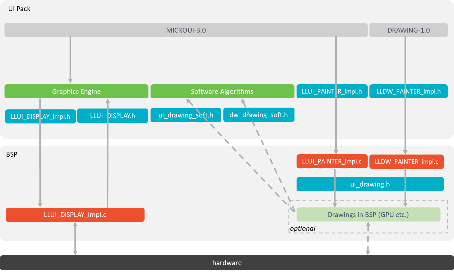
MicroUI library calls the BSP functions through the Graphics Engine and header file
LLUI_DISPLAY_impl.h.Implementation of
LLUI_DISPLAY_impl.hcan call Graphics Engine functions throughLLUI_DISPLAY.h.To perform some drawings, MicroUI uses
LLUI_PAINTER_impl.hfunctions.The MicroUI C module provides a default implementation of the drawing native functions of
LLUI_PAINTER_impl.handLLDW_PAINTER_impl.h:It implements the synchronization layer, then redirects drawings implementations to
ui_drawing.h.ui_drawing.his already implemented by built-in software algorithms (library provided by the UI Pack).It is possible to implement some of the
ui_drawing.hfunctions in the BSP to provide a custom implementation (for instance, a GPU).Custom implementation is still allowed to call software algorithms declared in
ui_drawing_soft.handdw_drawing_soft.h.
Display Size
The Abstraction Layer distinguishes between the display virtual size and the display physical size (in pixels).
The display virtual size is the size of the area where the drawings are visible. Virtual memory size is:
lcd_width * lcd_height * bpp / 8.The display physical size is the required memory size where the virtual area is located. On some devices, the memory width (in pixels) is higher than the virtual width. In this way, the graphics buffer memory size is:
memory_width * memory_height * bpp / 8.
Note
The physical size may not be configured; in that case, the Graphics Engine considers the virtual size os physical size.
Semaphores
The Graphics Engine requires two binary semaphores to synchronize its internal states.
These semaphores are reserved for the Graphics Engine.
The LLUI_DISPLAY_impl.h implementation is not allowed to use these semaphores to synchronize the function LLUI_DISPLAY_IMPL_flush() with the display driver (or for any other synchronization actions).
The implementation must create its semaphores in addition to these dedicated Graphics Engine’s semaphores.
The binary semaphores must be configured in a state such that the semaphore must first be given before it can be taken (this initialization must be performed in the LLUI_DISPLAY_IMPL_initialize function).
Required Abstraction Layer API
Four Abstraction Layer APIs are required to connect the Graphics Engine to the display driver.
The functions are listed in LLUI_DISPLAY_impl.h.
LLUI_DISPLAY_IMPL_initialize: The initialization function is called when the application is calling MicroUI.start(). Before this call, the display is useless and doesn’t need to be initialized. This function consists in initializing the LCD driver and filling the given structureLLUI_DISPLAY_SInitData. This structure has to contain pointers on the two binary semaphores, the back buffer address (see Display Configuration), the display virtual size in pixels (lcd_widthandlcd_height), and optionally the display physical size in pixels (memory_widthandmemory_height).LLUI_DISPLAY_IMPL_binarySemaphoreTakeandLLUI_DISPLAY_IMPL_binarySemaphoreGive: Two distinct functions have to be implemented to take and give a binary semaphore.LLUI_DISPLAY_IMPL_flush: According to the display buffer policy (see Display Configuration), theflushfunction has to be implemented. This function must not block and not perform the flush directly. Another OS task or dedicated hardware must be configured to perform the flush.
Optional Abstraction Layer API
Several optional Abstraction Layer APIs are available in LLUI_DISPLAY_impl.h.
They are already implemented as weak functions in the Graphics Engine and return no error.
These optional features concern the display backlight and contrast, display characteristics (is colored display, double buffer), color conversions (see Pixel Structure and CLUT), etc.
Refer to each function comment to have more information about the default behavior.
Painter Abstraction Layer API
All MicroUI drawings (available in the Painter class) call a native function.
The MicroUI native drawing functions are listed in LLUI_PAINTER_impl.h.
The principle of implementing a MicroUI drawing function is described in the chapter Drawings.
Graphics Engine API
The Graphics Engine provides a set of functions to interact with the C archive. The functions allow the retrieval of some drawing characteristics, the synchronization of drawings between them, the notification of the end of flush and drawings, etc.
The functions are available in LLUI_DISPLAY.h.
Most APIs are thread-safe, meaning that any C task can call the Graphics Engine APIs at any time.
However, some functions need to be synchronized with MicroUI (and the Core Engine task), including allocateImageBuffer(), freeImageBuffer(), and decodeImage().
Note
This list is not exhaustive; please refer to the C documentation for LLUI_DISPLAY_IMPL_lockJob() for the complete list.
To facilitate this synchronization, the Graphics Engine provides optional supplementary Abstract Layer API: LLUI_DISPLAY_IMPL_lockJob() and LLUI_DISPLAY_IMPL_unlockJob().
The implementation of these APIs simply involves using a binary semaphore.
Important
This binary semaphore must not be shared with the binary semaphores given to the Graphics Engine during its initialization.
Typical Implementations
This chapter helps to write some basic LLUI_DISPLAY_impl.h implementations according to the display buffer policy (see Display Configuration).
The pseudo-code calls external functions such as LCD_DRIVER_xxx or DMA_DRIVER_xxx to symbolize the use of external drivers.
Note
The pseudo code does not use the const ui_rect_t areas[] bounds to simplify the reading.
Common Functions
The three functions LLUI_DISPLAY_IMPL_initialize, LLUI_DISPLAY_IMPL_binarySemaphoreTake and LLUI_DISPLAY_IMPL_binarySemaphoreGive are often the same.
The following example shows an implementation with FreeRTOS.
void LLUI_DISPLAY_IMPL_initialize(LLUI_DISPLAY_SInitData *init_data) {
   // fill the LLUI_DISPLAY_SInitData structure
   init_data->binary_semaphore_0 = (void*)xSemaphoreCreateBinary();
   init_data->binary_semaphore_1 = (void*)xSemaphoreCreateBinary();
   init_data->lcd_width = LCD_DRIVER_get_width();
   init_data->lcd_height = LCD_DRIVER_get_height();
   /* init_data->back_buffer_address = [...]; see next chapters */
}

void LLUI_DISPLAY_IMPL_binarySemaphoreTake(void *sem) {
   xSemaphoreTake((xSemaphoreHandle)sem, portMAX_DELAY);
}

void LLUI_DISPLAY_IMPL_binarySemaphoreGive(void *sem, bool under_isr) {
   if (under_isr) {
      portBASE_TYPE xHigherPriorityTaskWoken = pdFALSE;
      xSemaphoreGiveFromISR((xSemaphoreHandle)sem, &xHigherPriorityTaskWoken);
      if (xHigherPriorityTaskWoken != pdFALSE) {
         // Force a context switch here.
         portYIELD_FROM_ISR(xHigherPriorityTaskWoken);
      }
   }
   else {
      xSemaphoreGive((xSemaphoreHandle)sem);
   }
}
Direct Buffer (parallel)
This policy considers the application and the LCD driver share the same buffer.
In other words, all drawings made by the application are immediately shown on the display.
This particular case is the easiest to write because the flush() stays empty:
void LLUI_DISPLAY_IMPL_initialize(LLUI_DISPLAY_SInitData *init_data) {
   // [...]

   // use same buffer between the LCD driver and the Graphics Engine
   LCD_DRIVER_initialize(lcd_buffer);
   init_data->back_buffer_address = lcd_buffer;
}

void LLUI_DISPLAY_IMPL_flush(MICROUI_GraphicsContext *gc, uint8_t flush_identifier, const ui_rect_t areas[], size_t length) {
   // nothing to flush to the LCD, just have to unlock the Graphics Engine by giving the same buffer address
   LLUI_DISPLAY_setBackBuffer(flush_identifier, LLUI_DISPLAY_getBufferAddress(&gc->image), false);
}
Swap Double Buffer (parallel)
This buffer policy requires two buffers in RAM.
The first buffer is used by the application (buffer A), and the LCD controller uses the second buffer to update the display panel (buffer B).
The LCD controller is reconfigured to use the buffer A when the Graphics Engine calls the flush() function.
Before executing the next application drawing after a flush, the Graphics Engine automatically waits for the end of the flush buffer processing: buffer B (which currently used by the LDC controller) is updated at the end of the swap.
The LCD driver is responsible for unlocking the Graphics Engine by calling the function LLUI_DISPLAY_setBackBuffer() at the end of the swap.
static uint8_t *buffer_A;
static uint8_t *buffer_B;
static uint8_t _flush_identifier;

void LLUI_DISPLAY_IMPL_initialize(LLUI_DISPLAY_SInitData *init_data) {
   // [...]

   // use two distinct buffers between the LCD driver and the Graphics Engine
   LCD_DRIVER_initialize(buffer_B);
   init_data->back_buffer_address = buffer_A;
}

void LLUI_DISPLAY_IMPL_flush(MICROUI_GraphicsContext *gc, uint8_t flush_identifier, const ui_rect_t areas[], size_t length) {
   // store the identifier of the flush used to unlock the Graphics Engine later
   _flush_identifier = flush_identifier;

   // change the LCDC address (executed at the next LCD refresh loop)
   LCDC_set_address(LLUI_DISPLAY_getBufferAddress(&gc->image));
}

// only called when reloading a new LCDC address
void LCDC_RELOAD_IRQHandler(void) {
   LCDC_DRIVER_clear_interrupt();

   // end of the swap, unlock the Graphics Engine, update the back buffer address
   uint8_t *new_back_buffer = (LCDC_get_address() == buffer_A) ? buffer_B : buffer_A;
   LLUI_DISPLAY_setBackBuffer(_flush_identifier, new_back_buffer, true); // true: called under interrupt
}
Swap Triple Buffer (parallel)
The behavior of this policy is very similar to that of the double buffer policy (see above): it consists in alternating between three buffers instead of two.
Single Buffer (serial)
A display connected to the CPU through a serial bus (DSI, SPI, etc.) requires the single buffer policy: the application uses a buffer to perform its drawings, and the buffer’s content has to be transmitted to the display when the Graphics Engine is calling the flush() function.
The specification of the flush() function is to be not blocker (atomic).
Its aim is to prepare / configure the serial bus and data to transmit and then to start the asynchronous transmission.
The flush() function has to return as soon as possible.
Before executing the next application drawing after a flush, the Graphics Engine automatically waits for the end of the serial data transmission: the back buffer (currently used by the serial device) is updated at the end of data transmission.
The serial device driver is responsible for unlocking the Graphics Engine by calling the function LLUI_DISPLAY_setBackBuffer() at the end of the transmission.
There are two use cases:
Hardware
The serial data transmission is performed in hardware. In that case, the serial driver must configure an interrupt to be notified about the end of the transmission.
static uint8_t _flush_identifier;

void LLUI_DISPLAY_IMPL_initialize(LLUI_DISPLAY_SInitData *init_data) {
   // [...]

   LCD_DRIVER_initialize();
   init_data->back_buffer_address = back_buffer;

   // initialize the serial driver & device: GPIO, etc.
   SERIAL_DRIVER_initialize();
}

void LLUI_DISPLAY_IMPL_flush(MICROUI_GraphicsContext *gc, uint8_t flush_identifier, const ui_rect_t areas[], size_t length) {
   // store the identifier of the flush used to unlock the Graphics Engine later
   _flush_identifier = flush_identifier;

   // configure the serial device to transmit n bytes
   // srcAddr == back_buffer
   SERIAL_DRIVER_prepare_transmit(srcAddr, LCD_WIDTH * LCD_HEIGHT * LCD_BPP / 8);

   // configure the "end of transmission" interrupt
   SERIAL_DRIVER_enable_interrupt(END_OF_TRANSMIT);

   // start the transmission
   SERIAL_DRIVER_start();
}

void SERIAL_DEVICE_IRQHandler(void) {
   SERIAL_DRIVER_clear_interrupt();
   SERIAL_DRIVER_disable_interrupt(END_OF_TRANSMIT);

   // end of transmission, unlock the Graphics Engine without changing the back buffer address
   LLUI_DISPLAY_setBackBuffer(_flush_identifier, back_buffer, true); // true: called under interrupt
}
Software
The serial data transmission cannot be performed in hardware or requires a software loop to transmit all data.
This transmission must not be performed in the flush() function (see above).
A dedicated OS task is required to perform this transmission.
static void *_transmit_task_semaphore;
static uint8_t _flush_identifier;

static void _task_flush(void *p_arg) {
   while(1) {
      // wait until the Graphics Engine gives the order to flush
      LLUI_DISPLAY_IMPL_binarySemaphoreTake(_transmit_task_semaphore);

      // transmit data
      SERIAL_DRIVER_transmit_data(back_buffer, LCD_WIDTH * LCD_HEIGHT * LCD_BPP / 8);

      // end of flush, unlock the Graphics Engine without changing the back buffer address
      LLUI_DISPLAY_setBackBuffer(_flush_identifier, back_buffer, false); // false: called outside interrupt
   }
}

void LLUI_DISPLAY_IMPL_initialize(LLUI_DISPLAY_SInitData *init_data) {
   // [...]

   LCD_DRIVER_initialize();
   init_data->back_buffer_address = back_buffer;

   // create a "flush" task and a dedicated semaphore
   _transmit_task_semaphore = (void*)xSemaphoreCreateBinary();
   xTaskCreate(_task_flush, "FlushTask", 1024, NULL, 12, NULL);
}

void LLUI_DISPLAY_IMPL_flush(MICROUI_GraphicsContext *gc, uint8_t flush_identifier, const ui_rect_t areas[], size_t length) {
   // store the identifier of the flush used to unlock the Graphics Engine later
   _flush_identifier = flush_identifier;

   // unlock the flush task
   LLUI_DISPLAY_IMPL_binarySemaphoreGive(_transmit_task_semaphore, false);
}
Single Buffer (parallel) and Tearing Disabled
Note
This policy should synchronize the copy buffer process with the LCD tearing signal. However, this notion is sometimes not available. This chapter describes the copy buffer process without using the tearing signal (see next chapter).
This buffer policy requires two buffers in RAM.
The first buffer is used by the application (back buffer), and the LCD controller uses the second buffer to update the display panel (front buffer).
The content of the front buffer must be updated with the content of the back buffer when the Graphics Engine is calling the flush() function.
The specification of the flush() function is to be not blocker (atomic, see above).
Its aim is to prepare / configure the copy buffer process and then start the asynchronous copy.
The flush() function has to return as soon as possible.
Before executing the next application drawing after a flush, the Graphics Engine automatically waits for the end of the copy buffer process: the back buffer (currently used by the copy buffer process) is updated at the end of the copy.
The copy driver is responsible for unlocking the Graphics Engine by calling the function LLUI_DISPLAY_setBackBuffer() at the end of the copy.
There are two use cases:
Hardware
The copy buffer process is performed in hardware (DMA). In that case, the DMA driver must configure an interrupt to be notified about the end of the copy.
static uint8_t _flush_identifier;

void LLUI_DISPLAY_IMPL_initialize(LLUI_DISPLAY_SInitData *init_data) {
   // [...]

   // use two distinct buffers between the LCD driver and the Graphics Engine
   LCD_DRIVER_initialize(frame_buffer);
   init_data->back_buffer_address = back_buffer;

   // initialize the DMA driver: GPIO, etc.
   DMA_DRIVER_initialize();
}

void LLUI_DISPLAY_IMPL_flush(MICROUI_GraphicsContext *gc, uint8_t flush_identifier, const ui_rect_t areas[], size_t length) {
   // store the identifier of the flush used to unlock the Graphics Engine later
   _flush_identifier = flush_identifier;

   // configure the DMA to copy n bytes
   // back_buffer == LLUI_DISPLAY_getBufferAddress(&gc->image)
   DMA_DRIVER_prepare_sent(frame_buffer, back_buffer, LCD_WIDTH * LCD_HEIGHT * LCD_BPP / 8); // dest / src / size

   // configure the "end of copy" interrupt
   DMA_DRIVER_enable_interrupt(END_OF_COPY);

   // start the copy
   DMA_DRIVER_start();
}

void DMA_IRQHandler(void) {
   DMA_DRIVER_clear_interrupt();
   DMA_DRIVER_disable_interrupt(END_OF_COPY);

   // end of copy, unlock the Graphics Engine without changing the back buffer address
   LLUI_DISPLAY_setBackBuffer(_flush_identifier, back_buffer, true); // true: called under interrupt
}
Software
The copy buffer process cannot be performed in hardware or requires a software loop to copy all data (DMA linked list).
This copy buffer process must not be performed in the flush() function.
A dedicated OS task is required to perform this copy.
static void *_copy_task_semaphore;
static uint8_t _flush_identifier;

static void _task_flush(void *p_arg) {
   while(1) {
      int32_t size = LCD_WIDTH * LCD_HEIGHT * LCD_BPP / 8;
      uint8_t *dest = frame_buffer;
      uint8_t *src = back_buffer;

      // wait until the Graphics Engine gives the order to copy
      LLUI_DISPLAY_IMPL_binarySemaphoreTake(_copy_task_semaphore);

      // copy data
      while(size) {
         int32_t s = min(DMA_MAX_SIZE, size);
         DMA_DRIVER_copy_data(dest, src, s); // dest / src / size
         dest += s;
         src += s;
         size -= s;
      }

      // end of copy, unlock the Graphics Engine without changing the back buffer address
      LLUI_DISPLAY_setBackBuffer(_flush_identifier, back_buffer, false); // false: called outside interrupt
   }
}

void LLUI_DISPLAY_IMPL_initialize(LLUI_DISPLAY_SInitData *init_data) {
   // [...]

   // use two distinct buffers between the LCD driver and the Graphics Engine
   LCD_DRIVER_initialize(frame_buffer);
   init_data->back_buffer_address = back_buffer;

   // create a "flush" task and a dedicated semaphore
   _copy_task_semaphore = (void*)xSemaphoreCreateBinary();
   xTaskCreate(_task_flush, "FlushTask", 1024, NULL, 12, NULL);
}

void LLUI_DISPLAY_IMPL_flush(MICROUI_GraphicsContext *gc, uint8_t flush_identifier, const ui_rect_t areas[], size_t length) {
   // store the identifier of the flush used to unlock the Graphics Engine later
   _flush_identifier = flush_identifier;

   // unlock the copy task
   LLUI_DISPLAY_IMPL_binarySemaphoreGive(_copy_task_semaphore, false);
}
Single Buffer (parallel) and Tearing Enabled
This buffer policy is the same as the previous chapter, but it uses the LCD tearing signal to synchronize the LCD refresh rate with the copy buffer process.
The copy buffer process should not start during the call of flush() but should wait for the next tearing signal to start the copy.
There are two use cases:
Hardware
static uint8_t _start_DMA;
static uint8_t _flush_identifier;

void LLUI_DISPLAY_IMPL_initialize(LLUI_DISPLAY_SInitData *init_data) {
   // [...]

   // use two distinct buffers between the LCD driver and the Graphics Engine
   LCD_DRIVER_initialize(frame_buffer);
   init_data->back_buffer_address = back_buffer;

   // enable the tearing interrupt
   _start_DMA = 0;
   TE_enable_interrupt();

   // initialize the DMA driver: GPIO, etc.
   DMA_DRIVER_initialize();
}

void LLUI_DISPLAY_IMPL_flush(MICROUI_GraphicsContext *gc, uint8_t flush_identifier, const ui_rect_t areas[], size_t length) {
   // store the identifier of the flush used to unlock the Graphics Engine later
   _flush_identifier = flush_identifier;

   // configure the DMA to copy n bytes
   // back_buffer == LLUI_DISPLAY_getBufferAddress(&gc->image)
   DMA_DRIVER_prepare_sent(frame_buffer, back_buffer, LCD_WIDTH * LCD_HEIGHT * LCD_BPP / 8); // dest / src / size

   // configure the "end of copy" interrupt
   DMA_DRIVER_enable_interrupt(END_OF_COPY);

   // unlock the job of the tearing interrupt
   _start_DMA = 1;
}

void TE_IRQHandler(void) {
   TE_clear_interrupt();

   if (_start_DMA) {
      _start_DMA = 0;

      // start the copy
      DMA_DRIVER_start();
   }
}

void DMA_IRQHandler(void) {
   DMA_DRIVER_clear_interrupt();
   DMA_DRIVER_disable_interrupt(END_OF_COPY);

   // end of copy, unlock the Graphics Engine without changing the back buffer address
   LLUI_DISPLAY_setBackBuffer(_flush_identifier, back_buffer, true); // true: called under interrupt
}
Software
static void *_copy_task_semaphore;
static uint8_t _start_copy;
static uint8_t _flush_identifier;

static void _task_flush(void *p_arg) {
   while(1) {
      // wait until the Graphics Engine gives the order to copy
      LLUI_DISPLAY_IMPL_binarySemaphoreTake(_copy_task_semaphore);

      int32_t size = LCD_WIDTH * LCD_HEIGHT * LCD_BPP / 8;
      uint8_t *dest = frame_buffer;
      uint8_t *src = back_buffer;

      // copy data
      while(size) {
         int32_t s = min(DMA_MAX_SIZE, size);
         DMA_DRIVER_copy_data(dest, src, s); // dest / src / size
         dest += s;
         src += s;
         size -= s;
      }

      // end of copy, unlock the Graphics Engine without changing the back buffer address
      LLUI_DISPLAY_setBackBuffer(_flush_identifier, back_buffer, false); // false: called outside interrupt
   }
}

void LLUI_DISPLAY_IMPL_initialize(LLUI_DISPLAY_SInitData *init_data) {
   // [...]

   // use two distinct buffers between the LCD driver and the Graphics Engine
   LCD_DRIVER_initialize(frame_buffer);
   init_data->back_buffer_address = back_buffer;

   // create a "flush" task and a dedicated semaphore
   _copy_task_semaphore = (void*)xSemaphoreCreateBinary();
   xTaskCreate(_task_flush, "FlushTask", 1024, NULL, 12, NULL);

   // enable the tearing interrupt
   _start_copy = 0;
   TE_enable_interrupt();
}

void LLUI_DISPLAY_IMPL_flush(MICROUI_GraphicsContext *gc, uint8_t flush_identifier, const ui_rect_t areas[], size_t length) {
   // store the identifier of the flush used to unlock the Graphics Engine later
   _flush_identifier = flush_identifier;

   // unlock the job of the tearing interrupt
   _start_copy = 1;
}

void TE_IRQHandler(void) {
   TE_clear_interrupt();

   if (_start_copy) {
      _start_copy = 0;

      // unlock the copy task
      LLUI_DISPLAY_IMPL_binarySemaphoreGive(_copy_task_semaphore, true);
   }
}
Transmit and Swap Buffer
This buffer policy is a mix between the buffer policies Single and Swap Double.
It requires two back buffers: the application uses a buffer to perform its drawings and the second buffer is used to transmit the data to the display frame buffer when the Graphics Engine is calling the flush() function.
At the end of the transmission, the application buffer becomes the transmission buffer and vice-versa.
The subtlety consists in reusing the transmission buffer as the application buffer at the end of the transmission if, and only if, the application has not drawn anything yet in the current application buffer. This avoids handling the restoration of the past: the application reuses the same buffer as before the last flush.
This policy requires a dedicated OS task that will manage the transmission and the unlocking of the Graphics Engine by calling the function LLUI_DISPLAY_setBackBuffer().
The specification of the flush() function is to be non-blocking.
Its aim is to unlock the flush task.
The flush() function has to return as soon as possible.
As soon as a transmission is started, the second buffer is freed. The Graphics Engine does not need to wait for the end of the serial data transmission: the application can draw immediately in the new back buffer. Note that the second flush has to wait the end of the first flush (the end of the transmission) before configuring and launching a new transmission.
The serial data transmission is performed in hardware or in software. In hardware, the serial driver must configure an interrupt to be notified about the end of the transmission. In software, the transmission step is synchronous and blocking.
Note
This pseudo implementation considers a display with a serial connection but the reasoning is similar with a parallel connection.
static uint8_t _flush_identifier;
static uint8_t _buffer_index;
static void *_transmit_task_semaphore;
static uint8_t _flush_identifier;

static void _task_flush(void *p_arg) {
   while(1) {
      // wait until the Graphics Engine gives the order to flush
      LLUI_DISPLAY_IMPL_binarySemaphoreTake(_transmit_task_semaphore);

      // save the flush configuration: can be modified by the next call to flush() as soon as LLUI_DISPLAY_setBackBuffer() wakes up the Graphics Engine
      uint8_t flush_identifier = _flush_identifier;

      // retrieve the transmit buffer: the current back buffer
      uint8_t *transmit_buffer = back_buffers[_buffer_index];

      // swap both buffers (_buffer_index now points to the new back buffer)
      _buffer_index = (_buffer_index + 1) & ~1;

      // the new back buffer can be used for the next drawings
      if (LLUI_DISPLAY_setBackBuffer(flush_identifier, back_buffers[_buffer_index], false)) {

         // here: the Graphics Engine is unlocked, the application can draw in the new back buffer
         // **and** can call flush() again

         // configure and start the serial device to transmit n bytes (synchronous or asynchronous
         // transmission)
         SERIAL_DRIVER_transmit_data(transmit_buffer, LCD_WIDTH * LCD_HEIGHT * LCD_BPP / 8);

         // wait for the end of the transmission (blocking call or use an interrupt)
         SERIAL_DRIVER_transmit_wait();

         // here: the back buffer has been sent to the LCD, the buffer can be used again for the
         // next drawings only if no new drawing has been already performed in the current back
         // buffer

         // reuse the old back buffer if no drawing has been already performed
         if (LLUI_DISPLAY_setBackBuffer(flush_identifier, transmit_buffer, false)) {
            // the new back buffer is set: cancel the previous swap to synchronize the driver with
            // the Graphics Engine
            _buffer_index = (_buffer_index + 1) & ~1;
         }
         // else: too late to reuse this old transmission back buffer; nothing to do
      }
      else {
         // unexpected end of flush; the Graphics Engine keeps using the previous back buffer;
         // we have to cancel the buffer swap
         _buffer_index = (_buffer_index + 1) & ~1;
      }
   }
}


void LLUI_DISPLAY_IMPL_initialize(LLUI_DISPLAY_SInitData *init_data) {
   // [...]

   LCD_DRIVER_initialize();

   // buffer 0 is the first back buffer; buffer 1 is not used
   _buffer_index = 0;
   init_data->back_buffer_address = back_buffers[_buffer_index];

   // initialize the serial driver & device: GPIO, etc.
   SERIAL_DRIVER_initialize();

   // create a "flush" task and a dedicated semaphore
   _transmit_task_semaphore = (void*)xSemaphoreCreateBinary();
   xTaskCreate(_task_flush, "FlushTask", 1024, NULL, 12, NULL);
}

void LLUI_DISPLAY_IMPL_flush(MICROUI_GraphicsContext *gc, uint8_t flush_identifier, const ui_rect_t areas[], size_t length) {
   // store the flush identifier to unlock the Graphics Engine later
   _flush_identifier = flush_identifier;

   // unlock the flush task
   LLUI_DISPLAY_IMPL_binarySemaphoreGive(_transmit_task_semaphore, false);
}
Dependencies
MicroUI module (see MicroUI)
LLUI_DISPLAY_impl.himplementation if standard or custom implementation is chosen (see Dependencies and LLUI_DISPLAY: Display).The MicroUI C module.
Installation
The Display module is a sub-part of the MicroUI library.
When the MicroUI Pack module is installed, the Display module is automatically enabled.
When the MicroUI module is installed, the Display module must be installed in order to connect the physical display with the VEE Port. If not installed, the stub module will be used.
In the VEE Port configuration file, check UI > Display to install the Display module.
When enabled, the Display module must be configured. This configuration step is used to choose the kind of implementation (see Dependencies).
- In SDK 6, the configuration is done in the properties file
configuration.propertiesof the VEE Port project. All the properties names listed below must be prefixed by
com.microej.pack.display.. For example thebppproperties is defined by thecom.microej.pack.display.bppproperty.
In SDK 5, the configuration is done in the properties file display/display.properties.
The properties file must / can contain the following properties:
bpp[mandatory]: Defines the number of bits per pixel the display device is using to render a pixel. The expected value is one among these lists:Standard formats:
ARGB8888: Alpha 8 bits; Red 8 bits; Green 8 bits; Blue 8 bits,RGB888: Alpha 0 bit; Red 8 bits; Green 8 bits; Blue 8 bits (fully opaque),RGB565: Alpha 0 bit; Red 5 bits; Green 6 bits; Blue 5 bits (fully opaque),ARGB1555: Alpha 1 bit; Red 5 bits; Green 5 bits; Blue 5 bits (fully opaque or fully transparent),ARGB4444: Alpha 4 bits; Red 4 bits; Green 4 bits; Blue 4 bits,C4: 4 bits to encode linear grayscale colors between 0xff000000 and 0xffffffff (fully opaque),C2: 2 bits to encode linear grayscale colors between 0xff000000 and 0xffffffff (fully opaque),C1: 1 bit to encode grayscale colors 0xff000000 and 0xffffffff (fully opaque).
Custom formats:
32: up to 32 bits to encode Alpha, Red, Green, and Blue (in any custom arrangement),24: up to 24 bits to encode Alpha, Red, Green, and Blue (in any custom arrangement),16: up to 16 bits to encode Alpha, Red, Green, and Blue (in any custom arrangement),8: up to 8 bits to encode Alpha, Red, Green, and Blue (in any custom arrangement),4: up to 4 bits to encode Alpha, Red, Green, and Blue (in any custom arrangement),2: up to 2 bits to encode Alpha, Red, Green, and Blue (in any custom arrangement),1: 1 bit to encode Alpha, Red, Green, or Blue.
All other values are forbidden (throw a generation error).
byteLayout[optional, the default value is “line”]: Defines the pixels data order in a byte the display device is using. A byte can contain several pixels when the number of bits per pixel (see ‘bpp’ property) is lower than 8. Otherwise, this property is useless. Two modes are available: the next bit(s) on the same byte can target the next pixel on the same line or the same column. In the first case, when the end of the line is reached, the next byte contains the first pixels of the next line. In the second case, when the end of the column is reached, the next byte contains the first pixels of the next column. In both cases, a new line or a new column restarts with a new byte, even if some free bits remain in the previous byte.line: the next bit(s) on current byte contains the next pixel on same line (x increment),column: the next bit(s) on current byte contains the next pixel on the same column (y increment).
Note
Default value is ‘line’.
All other modes are forbidden (throw a generation error).
When the number of bits-per-pixels (see ‘bpp’ property) is higher or equal to 8, this property is useless and ignored.
memoryLayout[optional, the default value is “line”]: Defines the pixels data order in memory the display device is using. This option concerns only the display with a bpp lower than 8 (see ‘bpp’ property). Two modes are available: when the byte memory address is incremented, the next targeted group of pixels is the next group on the same line or the next group on the same column. In the first case, when the end of the line is reached, the next group of pixels is the first group of the next line. In the second case, when the end of the column is reached, the next group of pixels is the first group of the next column.line: the next memory address targets the next group of pixels on same line (x increment),column: the next memory address targets the next group of pixels on the same column (y increment).
Note
Default value is ‘line’.
All other modes are forbidden (throw a generation error).
When the number of bits-per-pixels (see ‘bpp’ property) is higher or equal to 8, this property is useless and ignored.
imageBuffer.memoryAlignment[optional, default value is “4”]: Defines the image memory alignment to respect when creating an image. This notion is useful when image drawings are performed by a third-party hardware accelerator (GPU): it can require some constraints on the image to draw. This value is used by the Graphics Engine when creating a dynamic image and by the image generator to encode a RAW image. See GPU Format Support and Customize MicroEJ Standard Format. Allowed values are 1, 2, 4, 8, 16, 32, 64, 128 and 256.imageHeap.size[optional, the default value is “not set”]: Defines the image heap size. It is useful to fix a VEE Port heap size when building firmware in the command line. When using a MicroEJ launcher, the size set in this launcher has priority over the VEE Port value.
Use
The MicroUI Display APIs are available in the class ej.microui.display.Display.